TVI Problem

Davis.zhou

Active member
Having the problem in getting the the TVI.
The press was calibrate and test OK around 30 days before doing this test.
The print report was attached.
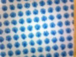
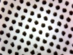
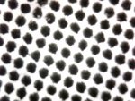
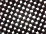
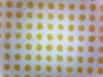
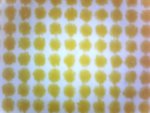
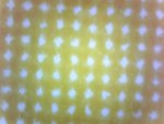
The screen dot of each color also attached.
No matter how to increase the ink film thickness, the Cyan and Yellow still remain at the similar position.
The M and Y TVi gavethe "M" shape.
Anyone can help?
 

Attachments

  • Measurement Report.pdf
    2.2 MB · Views: 256
  • C-25%.jpg
    C-25%.jpg
    54.5 KB · Views: 195
  • C-50%.jpg
    C-50%.jpg
    63.7 KB · Views: 181
  • C-75%.jpg
    C-75%.jpg
    63.9 KB · Views: 198
  • k-25%.jpg
    k-25%.jpg
    66.7 KB · Views: 200
The K and Y screen dot
 

Attachments

  • k-50%.jpg
    k-50%.jpg
    71.4 KB · Views: 172
  • k-75%.jpg
    k-75%.jpg
    77.1 KB · Views: 210
  • Y-25%.jpg
    Y-25%.jpg
    47.3 KB · Views: 191
  • Y-50%.jpg
    Y-50%.jpg
    51 KB · Views: 199
  • Y-75%.jpg
    Y-75%.jpg
    46.6 KB · Views: 187
Looking at the curves, I can't imagine that your plates are coming out correctly. Magenta in particular suggests you aren't sending the right dot to press. Do you have the ability to read the plate and compare with the dot values on the plate from your last calibration? That information would help in diagnosing . . .
 
Having the problem in getting the the TVI.
The press was calibrate and test OK around 30 days before doing this test.
The print report was attached.
The screen dot of each color also attached.
No matter how to increase the ink film thickness, the Cyan and Yellow still remain at the similar position.
The M and Y TVi gavethe "M" shape.
Anyone can help?

You have some serious problems.

I don't know what you mean by calibrating the press.

What I would do is start again from the beginning.

I overprinted the curves to make the problem more clear.
Curves.jpg

Notice the shape and clustering of the target curve (solid line) compared to the response you got on press for each color.

You should not try and fix that problem with more curves.
You need to find out if you have an ink lay down problem (which IMHO you do) or a plate curve problem - or a combination of both.

You should output either uncalibrated (no curves) or linear plates.

Print them to the appropriate densities don't be concerned with grey balance or dot gain.

Measure the SIDs, overprint traps, and dot gains.
If your inks are laying down properly you should get good solids (no voids/white specs), good trap values, and curves that have are clustered near each other and that have a similar shape. The shape and ink coverage of the dots should be similar to what is on the plates (your dots show signs of over emulsification).

If the curves end up being like the ones you posted (shapes are all different) then you have an ink lay down problem that needs to be fixed. If the curves are nested together then you can apply curves to achieve the tone values that you want.

More info here: Quality In Print: The principle of dot gain compensation plate curves

best, gordon p
 
Last edited:
Gordon,

Thanks for your comment.
You have some serious problems.

I don't know what you mean by calibrating the press.
I mean that the press was calibrated, such as roller strip (ink & water), packing, fountain solution, hardness of roller, etc.
What I would do is start again from the beginning.

I overprinted the curves to make the problem more clear.
Curves.jpg

Notice the shape and clustering of the target curve (solid line) compared to the response you got on press for each color.

You should not try and fix that problem with more curves.
You need to find out if you have an ink lay down problem (which IMHO you do) or a plate curve problem - or a combination of both.
We using the same brand of ink this time and which get the correct dot gain in last test.
Do not know IMHO meaning, please educate me.
Would you advise what would be the causes affect the color lay down?


You should output either uncalibrated (no curves) or linear plates.
We use the linear plate and the plate was checked before production, we did not apply any compensation curve in plate output.

Print them to the appropriate densities don't be concerned with grey balance or dot gain.
During the printing, we reach the aim target, actually, we use the ink density for production process control and after reach the target density, we will verify with the Lab value as well.

Measure the SIDs, overprint traps, and dot gains.
If your inks are laying down properly you should get good solids (no voids/white specs), good trap values, and curves that have are clustered near each other and that have a similar shape. The shape and ink coverage of the dots should be similar to what is on the plates (your dots show signs of over emulsification).
The pH value, conductivity and temperature of fountain also verified before testing.
After reaching the SID, and verify with LAB value, we found the TVI curve was abnormal, we tried to give more ink to check the TVI respond (keep the SID/Lab with in aim tolerances).
I need to point out that we allow a large tolerances on primary color (delta 6) and TVI (5%) because we need time to pick the experience on this.


If the curves end up being like the ones you posted (shapes are all different) then you have an ink lay down problem that needs to be fixed. If the curves are nested together then you can apply curves to achieve the tone values that you want.

More info here: Quality In Print: The principle of dot gain compensation plate curves

best, gordon p
 
IMHO means in my honest / humble opinion.

Having two bumps does make it seem that there is a curve or some other factor playing in. Are you using CTP or are you going via film? Is the lazer sharp enough?
You say you are using linear plates? That means you have a curve to make the plate linear? It could be that your linearisatino of plate is inaccurate, posibly due to the quality of the plate measuring equipment.
Try sending an uncompensated plate (measure it by all means but no compensation curve).
That means the stimulus is linear. When you make your plate linear you are adding a curve, if the curve is bad you are introducing error. Better to make one curve that does all the maths if your plate measuring equipment isn't capable of giving you an accurate curve.

Also would be interesting to know of other factors, plate type? Processing? etc.

Thanks for your comment and explanation.
We are using Kodak Trendsetter III with Pinergy Evo workflow and Kodak processor (all built in China), plate and developer also from Kodak (with consumable contract).
Basically, even we did not apply any adjustment in Harmony, the screen output difference is minimal (around 1 to 2%).
We are using X-Rite iC-Plate II Basic, the equipment just return from X-Rite (around 2 months ago) for annual calibration. We are operating under IS0-9001, we need to follow the ISO specification to ensure measurement devices are under well maintenance.
Plates output together with Kodak plate wedge. We also need to keep the record of the plate. We need to measure all plates after plate processing.
Track back the record, we did not found any plate having the problem in that day.
 
Just out of curiosity does anybody know from the target values in the report what the target standard is ?
As mention in my previous reply, the target value is a bit strange to other people. Which is the same as IS0-12647-2 Grade-1 paper (ISO-coated). But we modified the tolerances, to have a large Delta E on primary color C, M, Y, K.
Our Delta E is 6 instead of ISO - Delta E 5.
TVI is +/-5% instead of ISO - +/-4%.

We are very new in processing the printing standard. In this stage, we give a large tolerances to us to get enough experience. We are planning to tighten the tolerance to the same as ISO-12647-2 when we are comfortable with it.
 

PressWise

A 30-day Fix for Managed Chaos

As any print professional knows, printing can be managed chaos. Software that solves multiple problems and provides measurable and monetizable value has a direct impact on the bottom-line.

“We reduced order entry costs by about 40%.” Significant savings in a shop that turns about 500 jobs a month.


Learn how…….

   
Back
Top