LauraMinter
Member
Has anybody ever seen a 50% dot structure like this. I know it only reads 48% but I am more concerned about the structure of the dot than the calibration at this stage. It was done on a CTP device, 200lpi, 2400dpi and the platereader is a Lithocam. If we play out a 175lpi, we do not have the same problem. It is definately not a hardware problem because if you play out an internal test page at 200lpi, the dot structure is fine. So it is something to do with the algorithm of generating the dot structure. I am sure that it will not have a bearing on the quality of the print, although at this stage who knows. Any imput will be invaluable.
Kind regards
Kind regards
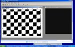
 2400 divided by 200 is 12, and the halftone cell is 12 x 12 pixels...