Can someone tell me where to find the tolerances that are used to judge proofs and press sheets for the G7 qualification process?
It is stated in several places in the GRACoL literature and it is based on ISO 12647-2
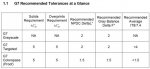
For the solids the tolerance is Delta E of 5 or less for all colors.
best, gordo
Colorblind, I looked at the link you provided, but I had always thought that these documents were for manufacturers to get their devices certified, not necessarily the tolerances for a sheet submitted for the G7 Master program.
But you're right, these documents are for proofing system vendors to get Gracol C1 - SWOP C3-C5 certified.
Gordon,
Do you have an idea of what the approximate density tolerances would be for the Delta E of 5 tolerances for the solids?
Just curious to see how wide they might be.
Thanks.
Thanks for the info. Maybe I should have provided more details. I'm not really concerned about the proofs. I was more concerned about doing a press test for GRACoL on a UV press. The green we are getting is 9 delta-E out but the other colors are close. It looks like we'll need to run it on the conventional press.
We've passed our G7 Master Printer in past years, (on a conventional press) but we never got any feedback about how close we were. Did we have a great sheet or did we just squeak by? I was trying to find out how they evaluate the sheet. For example, are they checking only the solids, traps and grays? I would assume they read the P2P target. If so, is there an acceptable number for the NPDC curve values? For the entire set of TVI swatches? Do they read the IT8 chart? If so, do they look at the average for the whole chart? For the best 90%? Do they look at the sigmas? Do they allow a higher delta-E for the dark 3-color swatches than they do for the bright colors?
No, I'd love to know as well. There are a few things that seem to remain secret about G7 and GRACoL 7 that no one who has gone through the process will talk about.
For example;
1) What are the center point SIDs that they arrived at once they hit the required CIELab values?
2) What SID variation is represented by a CIELab Delta E value of 5?
3) What were the base dot gain curves before G7 and what were they after?
4) Why does the GRACoL press operator guide specify that printing the targets should result in "measurements are within 1.5 delta C* of target" - but does not explain what "C*" is nor why they don't use L*a*b*
best, gordo
") Was fun trying to find the guide though !
Was fun trying to find the guide though !
View attachment 2500
My take on Question #1 is that every inkset will have a slightly different density once you hit the desired CIELab values, so they dont want to nail that one down....and thats why CIELab works so well. Its defining the color not density.
Question 2 is same as #1, it all comes down to the individual process and they will all be slightly different.
Question 3 is a Linear curve, after depends on press / paper / ink. Ive done all types of press / paper combinations and rarely do they ever come up the same for compensation curves
Question 4 I was only able to see this on the second to the last page of the press operators guide,tolerance for gray balance
and I have no idea
You will not find Density target Aims, Density variation and TVI numbers for G7, its only for process control after the calibration and thats it.
I'm pretty sure delta L is the L* difference without worrying about a* and b*. I would guess C is chroma. Maybe delta F is delta a and b without L? We care about hue but ignore lightness?
Rich,
Can you explain what delta C*, delta F*, and delta L* are?
Also, why are they being used rather than Delta E? What are their respective benefits? Perhaps how they are calculated?
So, what are the center point SIDs that different printers arrive at once they hit the required CIELab values?
|
A 30-day Fix for Managed Chaos
As any print professional knows, printing can be managed chaos. Software that solves multiple problems and provides measurable and monetizable value has a direct impact on the bottom-line. “We reduced order entry costs by about 40%.” Significant savings in a shop that turns about 500 jobs a month. Learn how……. |