Stephen Marsh
Well-known member
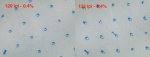
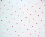
Today, I was taking some hand held digital microscope photos from a press fingerprint test run on clear poly film.
I thought that I would share the 0.4% highlight dot photos from the 133lpi and 120lpi test patches. The 0.4% dots print about the same size as the 1.2% dots.
The source file had a 0.4% dot. This was RIPed at 0.4% without a bump curve. The 0.4% dot was imaged to the TIL (thermal imaging layer, ablative mask film), then this was laminated to the NX plate (eliminates oxygen), exposed and processed etc.
Below are the final press results for your evaluation.
(Disclaimer, I work for a Kodak master distributor of the Flexcel NX flexographic system).
Stephen Marsh
Attachments
Last edited:
")