• Best Wishes to all for a Wonderful, Joyous & Beautiful Holiday Season, and a Joyful New Year!

True 0.4% highlight dot in flexo printed clear poly? Sure we can do that!

Stephen Marsh

Well-known member
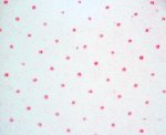
Today, I was taking some hand held digital microscope photos from a press fingerprint test run on clear poly film.

I thought that I would share the 0.4% highlight dot photos from the 133lpi and 120lpi test patches. The 0.4% dots print about the same size as the 1.2% dots.

The source file had a 0.4% dot. This was RIPed at 0.4% without a bump curve. The 0.4% dot was imaged to the TIL (thermal imaging layer, ablative mask film), then this was laminated to the NX plate (eliminates oxygen), exposed and processed etc.

Below are the final press results for your evaluation.

(Disclaimer, I work for a Kodak master distributor of the Flexcel NX flexographic system).


Stephen Marsh
 

Attachments

  • 0point4.jpg
    0point4.jpg
    473.9 KB · Views: 433
Last edited:
Hi Stephen,

At what % on your scales do you start seeing a more solid highlight dot or less halo'ing? That is a complaint i've heard about the NX plate is the highlights aren't improving, just the SID's.
 
Greetings Stephen,

What TVI do you think you would have measured if the dots were not printed as a donuts? I have tested NX plates on semi gloss and they do print some small dots - but we all know that film substrates have their own unique dot lay down challenges. Have you any photos of gray level 1 dots exposed and printed on a semi gloss? TVI of those dots?
 
Hi Stephen,

At what % on your scales do you start seeing a more solid highlight dot or less halo'ing? That is a complaint i've heard about the NX plate is the highlights aren't improving, just the SID's.


I personally would consider being able to hold a 0.4% dot from the RIPed file to plate to press - without a bump curve, at 120 or 133lpi to be an improvement, particularly so for this client that could not do this previously (without factoring in all of the other benefits).


Stephen Marsh
 
Today, I was taking some hand held digital microscope photos from a press fingerprint test run on clear poly film.

I thought that I would share the 0.4% highlight dot photos from the 133lpi and 120lpi test patches. The 0.4% dots print about the same size as the 1.2% dots.

The source file had a 0.4% dot. This was RIPed at 0.4% without a bump curve. The 0.4% dot was imaged to the TIL (thermal imaging layer, ablative mask film), then this was laminated to the NX plate (eliminates oxygen), exposed and processed etc.

Below are the final press results for your evaluation.

(Disclaimer, I work for a Kodak master distributor of the Flexcel NX flexographic system).


Stephen Marsh

I think some clarification is needed.

At 2540 dpi a 1% dot at 133 lpi is 19 microns - at 120 lpi it's 21 microns. Basically a 4 pixel structure - 4 ten micron pixels clustered to form the 1% dot.

At 2400 dpi a 1% dot at 133 lpi is 21 microns - at 120 lpi it's 20 microns. Again basically a 4 pixel structure - 4 ten point six micron pixels clustered to form the 1% dot.

You wrote: "The 0.4% dots print about the same size as the 1.2% dots."

Put another way, it can print a dot made up of 4 pixels. They are not 0.4% halftone dots. The tone area (which is made up of many halftone dots) may measure 0.4% but the individual halftone dots are still made up of clusters of 4 pixels - i.e. 1% or 1.2% dots.

I don't think the "source file had a 0.4% dot." It may have had a tone request of 0.4% which is not the same thing.

best, gordo
 
Last edited:
I think some clarification is needed.

At 2540 dpi a 1% dot at 133 lpi is 19 microns - at 120 lpi it's 21 microns. Basically a 4 pixel structure - 4 ten micron pixels clustered to form the 1% dot.

At 2400 dpi a 1% dot at 133 lpi is 21 microns - at 120 lpi it's 20 microns. Again basically a 4 pixel structure - 4 ten point six micron pixels clustered to form the 1% dot.

You wrote: "The 0.4% dots print about the same size as the 1.2% dots."

Put another way, it can print a dot made up of 4 pixels. They are not 0.4% halftone dots. The tone area (which is made up of many halftone dots) may measure 0.4% but the individual halftone dots are still made up of clusters of 4 pixels - i.e. 1% or 1.2% dots.

I don't think the "source file had a 0.4% dot." It may have had a tone request of 0.4% which is not the same thing.

best, gordo

Thanks Gordo, I think that I was a little loose with my wording!


Stephen Marsh
 
I personally would consider being able to hold a 0.4% dot from the RIPed file to plate to press - without a bump curve, at 120 or 133lpi to be an improvement, particularly so for this client that could not do this previously (without factoring in all of the other benefits).


Stephen Marsh

Good to hear, do you have any other info on the run? Machine, tape, anilox, speed etc.

Regarding Gordo's post below, was this ripped at 4000dpi which would make this an even smaller dot of about 12 microns? Correct me if I'm wrong, quick math.
 
Good to hear, do you have any other info on the run? Machine, tape, anilox, speed etc.

Regarding Gordo's post below, was this ripped at 4000dpi which would make this an even smaller dot of about 12 microns? Correct me if I'm wrong, quick math.


I was not given any other info on the run, I was just asked to take some photos.

2pt serif type is legible under a glass. 4pt serif type is legible to the eye. As it appears that the press operator squashed this a bit, the 1pt text would probably have survived a less heavy hand.

The cyan plate test files are standard TIFF files. My guess is that they are 2400, although they could be 2540. I’ll see if I can find out. The Kodak SquareSpot literature compares this to an effective resolution of 10,000 dpi imaging the 2400dpi pixels, with 10.4 micron dots being possible.

Please correct me if I am wrong, however I don’t believe that a small void in the centre of the highlight dots would be an issue, very much so for the human eye at fine linescreen rulings - or for instruments measuring density.


Stephen Marsh
 
Last edited:
No worries. Still, impressive for flexo. And I still love the FM cover printed flexo on film for the (defunct?) Kodak ONE magazine.

gordo

I have a copy of that issue right in front of me Gordo. It is a great showcase of what is possible with the Kodak Flexcel NX system.

20 micron stochastic screening on the front cover, 200 lpi on the inside front cover, printed on 5mil clear poly. The dots are very sharp, no voids in the centre of the highlights in either the stochastic or the halftone dots.


Stephen Marsh
 
I was not given any other info on the run, I was just asked to take some photos.

2pt serif type is legible under a glass. 4pt serif type is legible to the eye. As it appears that the press operator squashed this a bit, the 1pt text would probably have survived a less heavy hand.

The cyan plate test files are standard TIFF files. My guess is that they are 2400, although they could be 2540. I’ll see if I can find out. The Kodak SquareSpot literature compares this to an effective resolution of 10,000 dpi imaging the 2400dpi pixels, with 10.4 micron dots being possible.

Please correct me if I am wrong, however I don’t believe that a small void in the centre of the highlight dots would be an issue, very much so for the human eye at fine linescreen rulings - or for instruments measuring density.


Stephen Marsh

Been in Flexo, w/ NX Plates, for a while now. Those dots will never hold up. They will be dipping into the anilox and start splattering allover the place, as some of them are now doing. We use Hybird screening and had to increase the micron to get the dots to be consistence, for either stock of film. And that's what it is all about for long runs.
 
I want to share our experiences...As a company, we are following a different route. We have Esko Suite 12.1 (HD and Pixel+ addon), Pixel+ upgraded HD CDI and Digiflow Exposer. Simply we are creating 4000ppi 1bit tiff files and engrave directly (with higher amplitude) to digital dpr plate. We are not using any mask layer to prevent oxygen inhibition. Digiflow exposer uses pure nitrogene to create inert atmosphere.

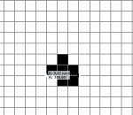
Check images. 70l/cm benchmark test print for clear poly. No bump.. 0,4% dot captured with Vipflex334. Measured dot diameter 22micron. Second image is 1bit tiff file 0,4% dot screenshot (0,2mm ~20micron).

The thing is, 0.4 percent dot can hold and print, but not suitable for long runs.

And yes, we made test runs with NX plates too...

Cheers.
 

Attachments

  • 04dot70lpcm.jpg
    04dot70lpcm.jpg
    165.7 KB · Views: 330
  • 04dot70lpcm1bit.jpg
    04dot70lpcm1bit.jpg
    47.5 KB · Views: 347
Check images. 70l/cm benchmark test print for clear poly. No bump.. 0,4% dot captured with Vipflex334. Measured dot diameter 22micron. Second image is 1bit tiff file 0,4% dot screenshot (0,2mm ~20micron).

The thing is, 0.4 percent dot can hold and print, but not suitable for long runs.

And yes, we made test runs with NX plates too...

Cheers.

What lpi are you running? As an FYI, 10 micron dot is a 1% dot at 2400 dpi. So I don't see how you are getting a .4% dot from a dot that's 20 microns (i.e. four 10 micron pixels)

Gordo
 
I want to share our experiences...As a company, we are following a different route. We have Esko Suite 12.1 (HD and Pixel+ addon), Pixel+ upgraded HD CDI and Digiflow Exposer. Simply we are creating 4000ppi 1bit tiff files and engrave directly (with higher amplitude) to digital dpr plate. We are not using any mask layer to prevent oxygen inhibition. Digiflow exposer uses pure nitrogene to create inert atmosphere.

Check images. 70l/cm benchmark test print for clear poly. No bump.. 0,4% dot captured with Vipflex334. Measured dot diameter 22micron. Second image is 1bit tiff file 0,4% dot screenshot (0,2mm ~20micron).

The thing is, 0.4 percent dot can hold and print, but not suitable for long runs.

And yes, we made test runs with NX plates too...

Cheers.


Hi Dersu, I have some questions, if I may…

By engrave, I presume that you mean directly ablate the thermal mask on the LAMs plate (as opposed to Kodak’s simple Thermal Ablative Film and Lamination method which is a much simpler method of removing oxygen from the exposure)?

As opposed to an engraving system such as:

graphics.kodak.com/au/en/product/flexographic/flexcel_direct_system/default.htm

How long did it take you to image a plate before the Digiflow upgrade?

How long does it take for a similar plate after the upgrade?

How much does nitrogen cost as a consumable and how much do you use per month?

From one of our customer’s experiences, the Flexcel NX system takes around 25% of the time to expose a plate as their CDI/LAMs plate setup. Their (non-digiflow) jobs would usually take an hour per plate before wash out, their Flexcel NX line only takes around 15 minutes for a comparable size plate/image before hitting the washer. I believe that Digiflow takes considerably longer to expose and uses more power. This customer has been courted by Digiflow and Lux methods with ongoing trials from their respective vendors and persistently continues to win awards with Flexcel NX, in addition to their standard CDI/LAMS setup.

As the saying goes “each to their own”!


Stephen Marsh
 
Last edited:
HI Dersu,

Do you know what kind of anilox line screen and what type of tape you use primarily on your print runs? Also what was your deciding factor on going with the DPR plate? Do you have any info on the kind of density you were getting as well?
 
Last edited:
What lpi are you running? As an FYI, 10 micron dot is a 1% dot at 2400 dpi. So I don't see how you are getting a .4% dot from a dot that's 20 microns (i.e. four 10 micron pixels)

Gordo


Hi Gordo. First, answer to your question it was 175lpi / 4000ppi plate.

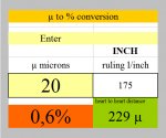
Well, yes this calculation bothers me since we received test plates from various companies (esko,dupont,flint etc.). All of them has 0,4 - 0,8 dots on their plates. In addition I have 1 bit tiff files. I measured all dots from source files as well as from plates. Theoretically %1dot at 2400ppi is 10micron. However I'm getting mixed answers from manufacturers. Can you please check attached file. I'm using this calculator sometimes. Honestly, I'm searching for a clear answer too.
 

Attachments

  • calc.jpg
    calc.jpg
    113 KB · Views: 344
By engrave, I presume that you mean directly ablate the thermal mask on the LAMs plate (as opposed to Kodak’s simple Thermal Ablative Film and Lamination method which is a much simpler method of removing oxygen from the exposure)?

I mean, We are exposing digital flexo plates with (Esko CDI) fiber laser sources. no masking films, no lamination.


How long did it take you to image a plate before the Digiflow upgrade?

How long does it take for a similar plate after the upgrade?

Digiflow or Pixel+ upgrade does not affect the processing time.


How much does nitrogen cost as a consumable and how much do you use per month?

Zero. We have our own nitrogen generators.

From one of our customer’s experiences, the Flexcel NX system takes around 25% of the time to expose a plate as their CDI/LAMs plate setup. Their (non-digiflow) jobs would usually take an hour per plate before wash out, their Flexcel NX line only takes around 15 minutes for a comparable size plate/image before hitting the washer. I believe that Digiflow takes considerably longer to expose and uses more power. This customer has been courted by Digiflow and Lux methods with ongoing trials from their respective vendors and persistently continues to win awards with Flexcel NX, in addition to their standard CDI/LAMS setup.


If I did not misunderstood your sentence; True, it takes longer. We choose Esko HD&Digiflow route, because combination has flexibility. We are 'a kind of' repro house. We have hundreds of customers. Every customer means different printers, different print substrates. With this flexible combination, we can create absolute solutions. So far ;)

As the saying goes “each to their own”!

Yep!
 
HI Dersu,

Do you know what kind of anilox line screen and what type of tape you use primarily on your print runs? Also what was your deciding factor on going with the DPR plate? Do you have any info on the kind of density you were getting as well?

Hi,

Most anilox rollers has more than 800 line screen and they are using primarily lochmann 5.3.
We made trials for different plates, DPR is best so far. More than hundred benchmark tests shows; minimum density increase is 0,3, maximum increase 0.7.
 
Hi Gordo. First, answer to your question it was 175lpi / 4000ppi plate.

Well, yes this calculation bothers me since we received test plates from various companies (esko,dupont,flint etc.). All of them has 0,4 - 0,8 dots on their plates. In addition I have 1 bit tiff files. I measured all dots from source files as well as from plates. Theoretically %1dot at 2400ppi is 10micron. However I'm getting mixed answers from manufacturers. Can you please check attached file. I'm using this calculator sometimes. Honestly, I'm searching for a clear answer too.

Speculation - what I think may be happening is using the 4000 dpi to reduce the size of the imaging laser spot. That enhaces the edge sharpness of the resulting dot. That is akin to what Creo/kodak does with their SquareSpot imaging. It runs at an optical resolution of 10,000 dpi in order to more accurately image a 10 micron pixel.
Your calculator wouldn't take that into consideration.

Gordo
 
Hi,

Thanks for the information. I will post some of our results soon with similar material. We have the same set up as you for making plates.

Hi,

Most anilox rollers has more than 800 line screen and they are using primarily lochmann 5.3.
We made trials for different plates, DPR is best so far. More than hundred benchmark tests shows; minimum density increase is 0,3, maximum increase 0.7.
 

PressWise

A 30-day Fix for Managed Chaos

As any print professional knows, printing can be managed chaos. Software that solves multiple problems and provides measurable and monetizable value has a direct impact on the bottom-line.

“We reduced order entry costs by about 40%.” Significant savings in a shop that turns about 500 jobs a month.


Learn how…….

   
Back
Top