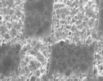
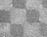
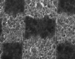
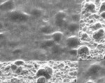
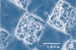
Here are electron-microscope images of plates from 3 CTCP systems compared to a thermal plate made on a Kodak SQUAREspot device.
You'll notice the difference in control/sharpness at the dot edges. This is due to the gaussian profile for the laser spot on CTCP (and non-SQUAREspot thermal devices), resulting in the edge exposure gradually fading instead of being cleanly cut off. That partially-exposed area is what's most sensitive to variation - in plate speed, processing, exposure, and other normal factors.
For coarse screens you won't see much effect from this - because the ratio of that "soft edge" to the size of each dot is pretty small. But once you get above 150lpi, the proportion of each dot that is "soft edge" grows considerably. This means you'll see more and more density change due to those variables as your screening goes up, and SQUAREspot will see considerably less (yes, we have data to prove that).
These were from plates I gathered personally from active user sites (mostly in Asia). What was interesting to me was that some of the systems had "reasonable" control in one axis (slow scan), the other axis was horrible. This causes another problem - as your variables change, you'll get a different level of effect on horizontal lines than you do on vertical ones. That can affect text as easily as it can screening or graphics.
Kevin.


