• Best Wishes to all for a Wonderful, Joyous & Beautiful Holiday Season, and a Joyful New Year!

Consiistent-excessive dot gain/TVI on all units.

Thanks gordo.

The scope images are very helpful. Possibly too helpful :)

Now I'm questioning a lot of what I could never see before.

For example…..


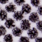
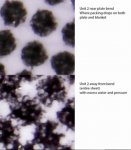
At first I thought this was over-emulsification, but looking at the ink in the plate bend, I now think it's just too much water?

Great! No shop should be without one of these inexpensive gizmos! It makes documenting press conditions, diagnosing ink issues, and communicating problems so much more effective.
 
In this case I posterized it first 'cause I thought that would be clearer. Here's the projection just using the source image:

Black%20Straight_zpsm85c4bew.jpg


With imageJ you can rotate the 3D projection as well as adjust height and granularity - so you see what's happening more clearly than just a single image shows.

Thanks again. And what about non-black ink? Especially yellow one? Do you convert it to any contrast color?
 
Thanks again. And what about non-black ink? Especially yellow one? Do you convert it to any contrast color?

ImageJ maps tone to height to get 3D. So if there's no difference in tone, as can be the case with Yellow, then I might take the Blue channel (which makes the RGB image yellow) and map that since it has the most contrast. With M and C the tone issue is not usually an issue.

Back in the day I used it to help visualize the different ink film thickness between AM and FM screens when both AM and FM tone patches measured as the same tone value with a spectrodensitometer.

Here's the 2D version:

AMFMSolidsm.jpg


Here's the 3D imageJ version:

3Dviewsm.jpg


Just another, perhaps a bit unconventional, way to try and understand what's going on presswise.

BTW, there's a very interesting little discoverable in the above 3D rendering. The ink film thickness is more homogenous across the surface of the FM dots compared to the AM dots. That variation in ink film thickness across the surface of the AM dots is caused by the snapping back of the ink on the dot as the paper passes through the nip. Much like how gum snaps back if you step on a patch of gum on the sidewalk. This variation in ink film thickness was sited in a TAGA paper as one of the reasons that AM dots result in a smaller gamut than FM dots.
 
Last edited:
Going back to the OP's issue. Now that there's a microscope in the house. What I would probably do is have a sit down with the press operator and show them the microphotos of well printed dots and the questionable dots. Then ask them - what they would do on press to make the dots look like the questionable/bad ones. Then, have the operator confirm that by going on press and forcing poor dot reproduction. That might provide an insight as to what caused the problem in the first place. If the operator doesn't know how to create the problem then he won't know how to solve in and you're in big trouble. Incidentally, it's a helpful test to give a prospective new pressman hire to ask them how they would create basic press problems.

On a sidebar, if you have press testing time it's a good idea to recreate the basic ink/press issues (like slur, doubling, over-emulsification, etc) then document how they were created and take photos. That way you'll have a in-house reference for when issues arise in the future.
 
"This variation in ink film thickness was sited in a TAGA paper as one of the reasons that AM dots result in a smaller gamut than FM dots."

Haven't seen the TAGA document (but would like to know which doc it is), but based on the 3D pics I would presume exactly the opposite. More homogenous yet less density. Trying to wrap my head around that claim.

I no longer have access to TAGA papers, maybe someone who has can find it. They included photos taken in the nip showing the ink splitting between blanket and paper - which looked just like the bubble gum analogy I used.

I didn't buy the argument when they published it. I think it was wrong.
IMHO, the difference in gamuts results from the size of the dots rather than how they're arranged. So, if you crank up the lpi of an AM screen so that it's dot structures are equivalent to those of an FM screen then the gamut sizes will align. I was one of the authors of a TAGA paper on this topic "The Lithographic Impact of Microdot Halftone Screening" 2003.
I could explain why AM FM gamuts are different as I/we did quite a bit of research on the subject at Creo to back up the marketing claims we were making at the time. But that is a different topic from this thread.
 
Now that I've sold a mess of microscopes to forum members - LOL - here's a little tip for the tip:

If you put frosted tape around the end of the scope you can mark it so that you have a guide to keep the view angle consistent from shot to shot.

MicroscopeNoseMarked_zps8g2fxj9b.jpg


Keeping the view angle consistent, among other things, is a big help when analyzing issues like slur and doubling.
 
Going back to the OP's issue. Now that there's a microscope in the house. What I would probably do is have a sit down with the press operator and show them the microphotos of well printed dots and the questionable dots. Then ask them - what they would do on press to make the dots look like the questionable/bad ones. Then, have the operator confirm that by going on press and forcing poor dot reproduction. That might provide an insight as to what caused the problem in the first place. If the operator doesn't know how to create the problem then he won't know how to solve in and you're in big trouble. Incidentally, it's a helpful test to give a prospective new pressman hire to ask them how they would create basic press problems.

On a sidebar, if you have press testing time it's a good idea to recreate the basic ink/press issues (like slur, doubling, over-emulsification, etc) then document how they were created and take photos. That way you'll have a in-house reference for when issues arise in the future.

That's a great idea.

Before I set up process controls, I should have processes for testing and fixing broken processes.

A "Bible" of benchmarks so to speak, that have explicit causes and fixes.


And now, from errors to Ayers.

Something in the back of my head tells me this has potential for ….
3Ddots.jpg
 
That's a great idea.

Before I set up process controls, I should have processes for testing and fixing broken processes.

A "Bible" of benchmarks so to speak, that have explicit causes and fixes.


And now, from errors to Ayers.

Something in the back of my head tells me this has potential for ….

I think I've created a monster! ROTFL

It's a lot of fun doing these - and one can get a bit carried away as I did back when...Take a peek at these halftone dots (scroll down a bit at the link):
http://the-print-guide.blogspot.ca/2010/08/halftones-as-youve-never-seen-them.html
 
That's a great idea.

Before I set up process controls, I should have processes for testing and fixing broken processes.

A "Bible" of benchmarks so to speak, that have explicit causes and fixes.

And now, from errors to Ayers.

Something in the back of my head tells me this has potential for ….

Damn, you've trapped pacman on the sheet!
 
Interesting. I thought that hiedelberg printing materials are just like manroland's printcom series – where printcom is just a label and who is producer nobody knows.

Saphira products are also just labeled by Heidelberg.
 
I wrote a 1997 TAGA paper related to this subject so I will make some comments that might help.

It has been known for a very long time that the rolling length of a soft roller does not usually equal the calculated length based on the diameter of that soft roller. For a rubber roller, the tested length usually is longer than the calculated length based on the diameter. So this lead to the concept of the "effective diameter" of the roller, which is usually larger than the actual diameter of the roller.

A rubber roller, when squeezed, deforms the rubber. This stretches the rubber surface at the nip and this stretching of the surface of the roller gives it the extra length.

Blankets are a little different because they are not made of a solid flexible material such as the robber roller, which does not lose volume when distorted. Blankets due to their construction, will deform and lose volume and this makes mathematical analysis difficult but it is relative easy to just test the blanket to determine its "effective diameter".

My TAGA paper was based on studies I did back in the mid 1980s on a web press to support our use of "insetting", which is the process of registering the print to a preprinted repeat length in the substrate. Insetting is very critical when one is running stiffer board than if one would run more normal substrates.

In those studies, the blankets we used showed an effective diameter that was slightly larger than the calculated diameter of the blanket cylinder. Also the effective diameter could be changed by changing the impression squeeze and also by changing the tension before and after the impression nip.

My view is that the difference in feed rate would not directly affect the dots. The differences in feed length are on the order of a fraction of 1% and this should not cause visible slur. Less than 1% distortion of a dot, that does not print sharp in the first place is not an issue. But different feed rates might affect the mechanical linkages in the press, gear etc. which might indirectly cause issues.

I could see that blanket manufacturers could design blankets with both positive and negative effective diameters. This might be more helpful on sheetfed presses than on web presses since on a sheet fed press the sheet is only held in place by the grippers and the sheet can distort under different printing conditions. In a web press, the web itself tends to help stabilize the substrate.

In general it is more important to have matching blankets in a press. Is is not as critical for a web press but it would be for a sheetfed press.

Hope this helps.

Thanks Erik, This was really helpful.
 
Hello aqazi81,


Fundamental that Identical Blankets be mounted on all blanket cylinders and crucial

for High Speed Commmercial Web Offset Presses running at 40,000 IPH or 7 meters per second.

Regards, Alois
 
Hello aqazi81,


Fundamental that Identical Blankets be mounted on all blanket cylinders and crucial

for High Speed Commmercial Web Offset Presses running at 40,000 IPH or 7 meters per second.

Regards, Alois

You are right Alois. Is this positive rolling theory also correct for sheetfed presses?
 
Hello aqazi81

Answer - I'm sceptical of the claims.


" Agood blanket-- like a good ink and good paper is the result of a comprise among

a number of oppossing characteristics" ----- Lithographic Technical Foundation


The main criteria are the Blanket Face and the Compressible Layer, this layer patented by the

manufacturers, depending on which of 4 types of compressible layer used, dictates on

press performance characteristics.

Next we come to the weaving and manufacture of the Cotton Fabric Layers, which is a topic

I will leave alone.


To the Naysayers, of necessity I've had to mix blankets on the press.


Regards, Alois
 
Now that there's a microscope (and the knowledge) to analyze the printed dots, has that offered a solution to the problem? It sounds like maybe it's an ink/water balance issue, or lack thereof. Science, or Craft, or both?

I am definitely much closer, thanks to gordo and the scope.
It appears the problem is two-fold.
1. Too much water resulting in chasing SID, then more water, etc. etc.

2. Pressures also seem a little heavy.
I've not determined where the excess pressure is yet, but my previous post about the plate bend was a clue to it being pressure.
The clean dot near the bend, is where the packing is dropping off. Whether it's plate, blanket, or both, I have yet to test.

Here's a sample of the excess water running on all units now and destroying the dot (emulsifying the ink) TooMuchWater.jpg
 
Same unit where packing drops and the remaining area of the sheet.

I'll doubt you can apply so much pressure to squash same dot to this condition.
Keeping in mind that we print the emulsion I would say that either there is too much water on the plate or there is a problem with metering roller angle to the transfer roller.
 
Mr. CClyde, how's your progress on dot gain problem?

Getting closer.

I've decided the best course is to take the time to document the set up on one unit from scratch.

The press operators have been setting up by the math where each spec is taken as true according to supplier's spec sheets. This doesn't take into account wear on the bearers, over-under spec on plate packing, blanket thickness, paper, roller dia. etc.

So I'm scheduling a full set up including micrometer readings on everything. Then we'll do a dry break away and record a value for the zero point.

Then we'll tackle the water amount and emulsification.

I've seen a consistent over-emulsification on long runs and after an equivalent series of short run jobs.

I think (hypothesis) what's happening is a snowball effect caused by increased pressures and too much water.

The increased pressures are small enough that they're not obvious on the blanket or sheet, but they cause the water take-up to increase more than normal with each impression. This with the elevated water results in a gradual transfer of micro drops of ink into the water and water into the ink. The initial transfer may be any one of number of contact points, but once it begins it transfers through the whole ink train and back through the water. By the time the press operator sees the effect it's too late. He assumes it's the plate not clearing (it is impossible to see the actual mechanics without the scope) so he chases it with more water to clear the plate, that drops his SID and the snowball is now in free-fall down the mountain.


I'll post the results on the first unit when we're done.
 

PressWise

A 30-day Fix for Managed Chaos

As any print professional knows, printing can be managed chaos. Software that solves multiple problems and provides measurable and monetizable value has a direct impact on the bottom-line.

“We reduced order entry costs by about 40%.” Significant savings in a shop that turns about 500 jobs a month.


Learn how…….

   
Back
Top