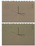
Moire pattern on offset anicolor press

jotterpinky

Well-known member
We've had a problem with our SM-52 anicolor off and on depending on artwork coloration with a moire pattern on certain tones, usually browns, and grays. We've discussed with Heidelberg several times and were told to run with a different screen angle. Come to find out it's the exact set of angles we were told to use when the press was installed. We're currently running a "CMYK +7.5" set of angles with an elliptical dot (172.5, 52.5, 7.5, and 112.5, CMYK respectively). I don't know much about moire patterns but the pattern we are seeing doesn't seem to make sense to me. If I swap the Cyan and Magenta angles we still get the same pattern and tone (pinkish tone). If we decrease the line ruling from our standard 200 lpi to 175 lpi the pattern becomes more apparent but also CHANGES ANGLES and DISTANCE between the pattern (see attached photo). This does not make sense as it seems that the pattern should keep the same angle if the screens are the same angle. Without fail the pattern always has a pink hue to it.

We've brought this up with our RIP vendor (Xitron Navigator RIP) and have received no help...they seem to be ignoring us.

Any ideas or thoughts? - see attachment for a visual, the top shot shows the pattern at 200 lpi, the bottom shows the pattern at 175 lpi
 

Attachments

  • moire-pattern-example.jpg
    moire-pattern-example.jpg
    50.7 KB · Views: 473
Last edited:
We've had a problem with our SM-52 anicolor since it was installed with a moire pattern on certain tones, usually browns, and grays. We've discussed with Heidelberg several times and were told to run with a different screen angle. Come to find out it's the exact set of angles we were told to use when the press was installed. We're currently running a "CMYK +7.5" set of angles with an elliptical dot (172.5, 52.5, 7.5, and 112.5, CMYK respectively). I don't know much about moire patterns but the pattern we are seeing doesn't seem to make sense to me. If I swap the Cyan and Magenta angles we still get the same pattern and tone (pinkish tone). If we decrease the line ruling from our standard 200 lpi to 175 lpi the pattern becomes more apparent but also CHANGES ANGLES and DISTANCE between the pattern (see attached photo). This does not make sense as it seems that the pattern should keep the same angle if the screens are the same angle. Without fail the pattern always has a pink hue to it.

We've brought this up with our RIP vendor (Xitron Navigator RIP) and have received no help...they seem to be ignoring us.

Any ideas or thoughts? - see attachment for a visual, the top shot shows the pattern at 200 lpi, the bottom shows the pattern at 175 lpi

Interesting problem. Normally moire patterns involve at least two printed screens. One can have moire with only one printed screen when the image is captured with a device such as a digital camera that has a grid pattern that captures the image. There is a term for this but just now I forget what it is called. I would think this type of moire would be visible in prepress.

Also since you are applying ink to the single form roller with an anilox roller, which is screened, this could be contributing to the moire. Try printing only one screen and see if there still is a moire. This would suggest that it is due to the screen capture of the image or the anilox screen inking of the form roller. If the moire is due to the anilox roller pattern, then this would not be seen in prepress.

Just some ideas.
 
Last edited by a moderator:
WWe've brought this up with our RIP vendor (Xitron Navigator RIP) and have received no help...they seem to be ignoring us.

Do you have HPS enabled in your Rip? You may want to try more standard screen angles (0°, 15°, 45°, and 75° or multiples of 90) and ensure HPS (Harlequin Precision Screening) enabled. HPS only works off standard angles and will automatically adjust line screen and angle to eliminate moire (as can be shown in the log as the file Rips). I found it a requirement for separations.
 
HPS is enabled on the RIP. If I turn it off (we've tried everything) I get the same pattern but repeated much more often (closer together). If we try more standard angles we've been told we might get interference with the anilox itself and are hence loath to do so.
 
Last edited:
What angle is your anilox...perhaps to close to magenta angle? I think the change in line screen from 200 to 175 might indeed cause an change in the moire angle & spacing as the interference with the static-angle anilox become less frequent.
 
What angle is your anilox...perhaps to close to magenta angle?

I should amend this to read "to close to the 52.5 angle", rather than specify magenta. Swapping magenta and cyan while still using an angle that may have interference with the anilox may still cause "pinkish" patterns.
 
Anilox Inking Roller

Anilox Inking Roller

Hello jotterpnky and gentlemen,

IMHO opinion, as already mentioned by Erik and Meddington, this points to - Screen Clash of Anilox Roller and

screen angles used.

1) read "Anilox Basics" from Zecher GmbH, Start.

or their U.S company Interflex Laser Engravers - Home.


Regards, Alois
 
Last edited:
"Alois" - We also had the idea that it might be a problem with the Anilox. However we are told by Heidelberg that this anilox uses a 10 micron cell size which should not interfere with the line screen at frequencies over 200 lpi. Not sure if this is true or not. If this was the case though why would we see the same problem when swapping the magenta and cyan angles....wouldn't we expect to see this follow whichever plate was using the troublesome angle?

By the way Meddington I noticed that the RIP does show a deviated frequency of 207 degrees rather than the 200 (for CMK, Y as is normal is around 221 lpi). One thing I haven't done is change the number of gray levels generated using HPS. It's currently set at 1024 gray levels which I believe if plenty but it does allow up to 4096 gray levels. I'm not sure what this actually does though. Do you know?
 
have you tried those plates on a different press. to rule out the plates. or have someone close make plates on a different type rip from your file and see what happens.
 
OK...

Moiré such as you're experiencing is caused by two two patterns (halftone screens) that are harmonically beating with one another.

The 7.5° offset is used to introduce "noise" in order to eliminate single channel moiré - moiré caused by the screen angle of one separation causing the halftone dots to have pixels on the edge of each halftone dot that themselves have a frequency. I.e. the frequency of the pixels on the edge of each halftone dot forming a repeating pattern that harmonically beat with the frequency of that individual separation - thereby causing a single channel moiré. That is a fairly standard workaround for elliptical screens. You could use a round dot instead to eliminate the need for the 7.5° offset.

Visible interchannel moiré is minimized when the halftone screens are at least 30° apart from one another. There are only three angles where this is possible in 4/C process. So one color will always be less than 30° from its neighbor and hence harmonically beat and result in moiré.

In your 4/C separations
Cyan, Magenta, and Black are 30° away from each other. So, by themselves, those won't show moiré between each other.
Yellow, however, is 15° away from K so, if there is a visible moiré between two colors it will be a Y/K moiré. However, the lpi of the Y separation is typically run at an lpi of 108% of the other process colors. That helps minimize the visibility of the moiré by increasing its periodicity. Y is also much lighter than K (or C and M) so that also helps to reduce the visibility of the moiré.

I don't know the specific screen angles of the anilox roller on your press however, because of the geometries the only screen angles that are available are 90°, 60°, 45°, and 30°

Due to mechanical and printing reasons the recommended angles are typically 45° or 60°.

That makes the most likely potential conflict between the anilox roller screen angle and your separations the M and C channels. (A color separation of 7,5° - 37,5° - 67,5° - 82,5° is based on the assumption that the anilox roller angle is at 45° add or subtract 90° to figure out your angles).

I suggest to ask HD what the lpi and screen angle of your anilox roller is. I think that is where your problem is.

More info on screen angles is here:
The Print Guide: Halftone screen angles

Some other notes: the moiré in digital images that Erik referred to is called a "Demosaicing moiré" - not your problem.

The Y channel is typically 108% of the lpi of the C, M, and K lpi (to minimize Y/X moiré).

If the lpi of the halftone screen is not an even divisor of the dpi of the recording device then a close compromise lpi will be used instead of the requested lpi. I.e. a 200 lpi request could result in a 207 or 196 lpi or something else. The RIP knows best.

The screen angles you are using place the K at a very visible angle - not ideal. It places the M at the least visible angle (45°). That was typically used when UCR separations were the norm as it placed the strong M color at the least visible angle (45°). With the GCR separations used today where K is the dominant color it is probably best to reserve the 45° (or 52.5° with your offset) for the K channel.

The grey levels setting is irrelevant. Basically once the classic output device lpi to dpi ratio is hit ((dpi/lpi) squared + 1 = number of grey levels) halftone dot dithering is used to create grey levels. That is explained here:
The Print Guide: Halftones and grey levels explained

Hope this helps.

Gordo
 
Last edited:
use fm screen instead of Am for yellow & ?----- see the magic ?


An elegant solution for moire, provided one owns the licensing for fm screening, and is prepared to compensate for different dot gain and gamut characteristics.
 
Last edited:
use fm screen instead of Am for yellow & ?----- see the magic ?

Using an FM screen for the Yellow works to get rid of Y/M or Y/C moirÄ— - but that doesn't appear to be the problem here. Probably a waste of effort.
BTW, using a coarse FM screen will usually bring its dot gain inline with the dot gain of the other colors.

Rather than throw any old "solution" at the problem, it would be more priductive to take a systematic step by step approach. That's why Erik's idea of outputting the individual screens rather than screen tint builds is good. If the moirÄ— is caused by the anilox screen then it should show up in one of the individual screens.

Gordo
 
Last edited:
moire-pattern-example-2.jpg

Gordo, the attached graphic shows some additional tests we've done. I have a hard time believing it's a problem with the anilox at this point since the pattern does not show when we image individual separations by themselves (i.e. only print the cyan, then only print magenta, etc). Wouldn't we see the moire if it was simply an interference with the anilox and a single color? The attached graphic shows the same moire pattern in the lady's pants. It doesn't appear on any of the duotones but as soon as we print a tri-tone (CMK) it shows. Does this make sense to anyone? Apparently the pattern is an interference that only happens when all three colors are present?

I'll try to change the dot shape to round and move the black to the 52.5 angle.
 
That is a different example from what you originally posted. Because this moirÄ— is happening on an image of fabric which likely has its own pattern - in this case you might be dealing with subject moirÄ— - i.e. The K screen angle/frequency may be clashing with the angle/pattern of the pants.
In this case changing the angle of the K may eliminate it.

Gordo
 
That picture is certainly more telling. If you routinely print images of patterned fabric, you may very well be better off investigating stochastic screening. Standard screening and angles that work fine for one image could lead to moire in another and you could be back at square one other-wise.
 
That is a different example from what you originally posted. Because this moirÄ— is happening on an image of fabric which likely has its own pattern - in this case you might be dealing with subject moirÄ— - i.e. The K screen angle/frequency may be clashing with the angle/pattern of the pants.
In this case changing the angle of the K may eliminate it.

Gordo

Gordon stated, "Erik referred to is called a "Demosaicing moiré" "

Is "Demosaicing moiré" the same as "subject moire"? What I was refering to was subject moire now that you reminded me of the term. With subject moire as I know it, one should not be able to correct it with any angles on the prepress work. It is in the captured original due to the image taken with a digital camera. I had read that this was a problem with fashion photography.

One way camera manufacturers tried to get around this problem was to move the image collector back plane when taking the shot in the camera a slight bit to slightly blur the image. Maybe this is not done anymore since the resolution has increased so much.
 
Gordon stated, "Erik referred to is called a "Demosaicing moiré" "

Is "Demosaicing moiré" the same as "subject moire"? What I was refering to was subject moire now that you reminded me of the term. With subject moire as I know it, one should not be able to correct it with any angles on the prepress work. It is in the captured original due to the image taken with a digital camera. I had read that this was a problem with fashion photography.

Basically yes. But the moirÄ— would be visible in the original image. It can be fixed but that's a complicated process. If the moirÄ— only appears in the presswork then it's still subject moirÄ— but the clash is the subject pattern with the halftone screen.

Gordo
 
From the second sample show I am almost certain its subject moiré, we used to correct this by applying a Gaussian blur in Photoshop over the selected article of clothing, if you have no control over the files try running this test again at 175LPI, I have found not only can screen angles clash with artifacts in an image also the screen frequency can clash with the weave or pattern of the fabric, try it and let us know
 

PressWise

A 30-day Fix for Managed Chaos

As any print professional knows, printing can be managed chaos. Software that solves multiple problems and provides measurable and monetizable value has a direct impact on the bottom-line.

“We reduced order entry costs by about 40%.” Significant savings in a shop that turns about 500 jobs a month.


Learn how…….

   
Back
Top